
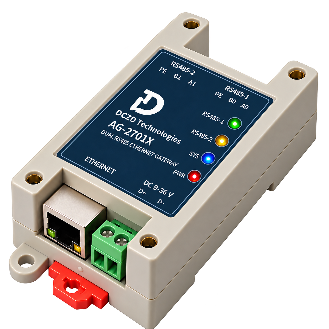
AG-2701X is a DIN rail dual-RS485 Ethernet gateway for the wired enterprise setup with M1 three-phase circuits and M4 single-phase branches. Appearance, panel and specifications follow the selected handbook dated 20 October 2026; product and installation images now carry the DCZD brand, with the AG-2701X model designation preserved.
Product specifications
| Ethernet | One RJ45, 10/100 Mbit/s; no PoE |
|---|---|
| RS485 | Two 2-wire half-duplex channels, each with A, B and ISOGND |
| Termination | 120 Ω on each channel, independently selected by the two-position DIP switch |
| Networking and connections | TCP Server and static IPv4; one raw TCP connection per P1/P2 plus one Modbus TCP connection |
| Modbus reads | Functions 03/04 on selected P1 or P2; 1–125 registers per request |
| Serial settings | 1200–512000 bit/s, fixed 8 data bits, none/odd/even parity, 1/2 stop bits |
| Power | A current-limited DC 24 V supply; 9–36 V is the design input range, with boundaries pending physical tests |
| Enclosure and mounting | DIN rail mounting; nominal L82 × W54 × H32 mm, mounting-ear span approximately 100.21 mm |
| Storage and maintenance | 4 MiB SPI Flash; web configuration, A/B web-resource updates and signed firmware maintenance |
| Indicators | Green RS485-1, yellow RS485-2, blue SYS, red PWR |
Two integration paths
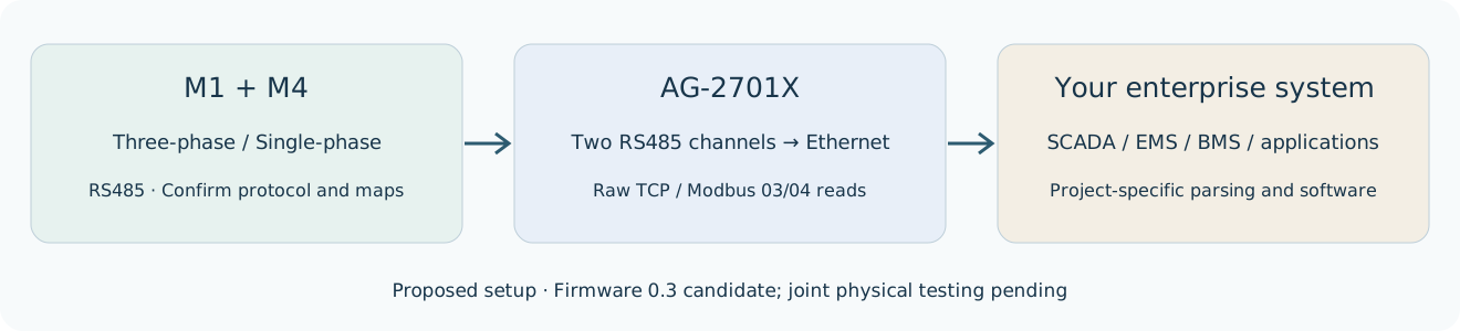
Raw TCP: P1/P2 use separate TCP Server ports, each with one client; both raw channels can run together. The host owns meter messages, RTU CRC, polling and decoding.
Modbus TCP to RTU: only function 03/04 reads are forwarded to the P1 or P2 selected in web configuration. Unit ID does not automatically route between channels. General downstream writes are not implemented, and raw TCP and Modbus cannot share one channel at the same time.
Wiring and panel clearance
P1 uses A0/B0/ISOGND and P2 uses A1/B1/ISOGND. The two channels share bus-side ground. The PE panel marking denotes ISOGND rather than protective earth. D+/D- are power polarity. Follow actual pin numbers and wiring documents rather than inferring left/right order from a photo.
Allow for the enclosure and approximately 100.21 mm ear span, then add RJ45 removal, terminal, DIP-switch and cable-bend clearances. Use the current-limited DC 24 V supply specified by the source handbook.
Configuration and maintenance
The local web interface provides status, network/serial settings, import/export and parameter saving. The 4 MiB Flash holds web resources, settings, staged firmware and the previous image. A/B web-resource updates, signed firmware installation, trial confirmation and recovery are firmware 0.3 software functions; physical workflows remain untested.
Product and industry handbooks
Download AG-2701X handbook (Traditional Chinese DCZD brand edition PDF)Download the industry handbook (Simplified Chinese PDF, V1.2)
When connecting field I/O
Add AC-2705X when equipment status and relay control are required. Keep the base metering setup and agree the read or raw-TCP write route and acceptance tests.