
Add AC-2705X for equipment status and control
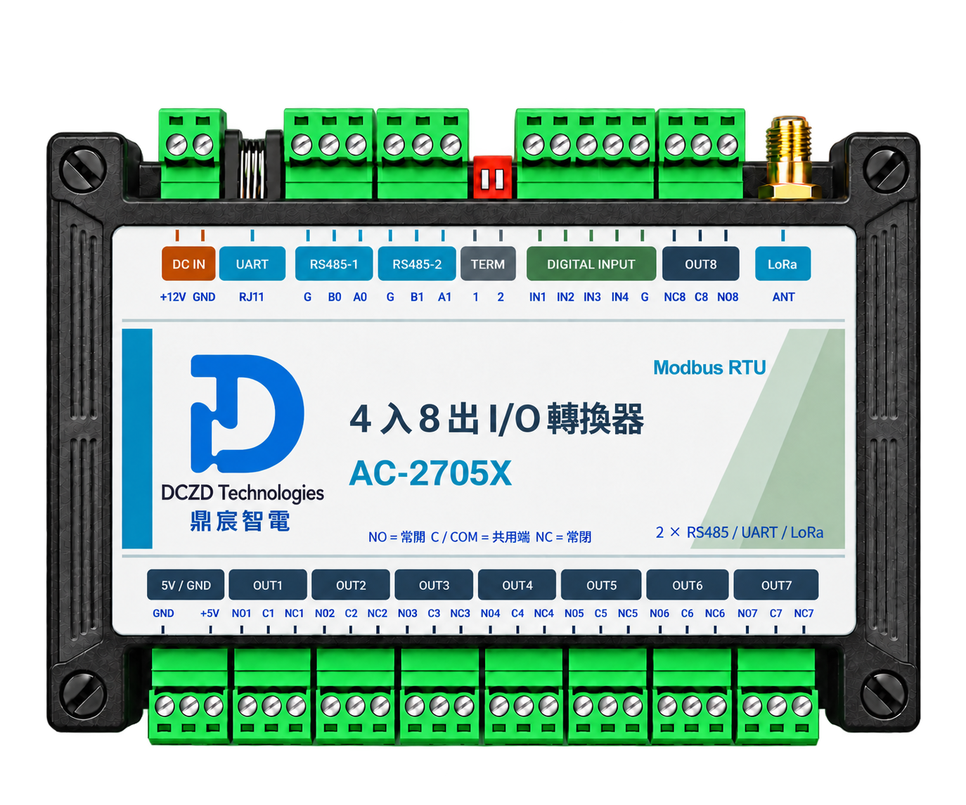
Extend the M1, M4 and AG-2701X collection setup with AC-2705X where needed: four isolated inputs collect status and eight relay outputs connect field controls. Confirm signals, loads and feedback before configuring equipment and software.
The site need it addresses
M1 and M4 provide meter readings. AC-2705X adds external digital run/fault status and relay outputs for commands issued by the host. AG-2701X connects wired RS485 to enterprise Ethernet. The project must define control policies, business decisions and actual-load feedback.
Core configuration
- Four isolated inputs and eight relay outputs.
- RS485 integration; configure reads, writes and device addresses against the agreed protocol.
- Provide input-signal and output-load schedules, wiring, feedback and failure-state requirements for the site.
Configuration and installation conditions
| Inputs | Four optocoupler-isolated inputs. The design high level is 3.3–9 V; production-board thresholds require retesting. Dry contacts need signal adaptation. |
|---|---|
| Outputs | Eight SPDT relays, NO/C/NC, with 5 A continuous per terminal. Confirm load voltage, type, inrush and thermal conditions for the site. |
| Power | AC-2705X uses DC 12 V. Do not connect it directly to the DC 24 V supply specified for AG. |
| Mounting and dimensions | DIN rail mounting; 149 × 108 × 41 mm, plus wiring and terminal access clearance. |
| Wired interfaces | Dual RS485 plus isolated TTL UART on RJ11. RJ11 is not Ethernet; TTL-to-RS485 requires an external transceiver. |
| Protocol and initial configuration | Modbus RTU; protocol 1.2 and code baseline 0.6.2 are candidates. Start integration checks at 9600 bit/s, 8N1. The default address is 1; assign unique addresses on a shared bus. |
| Event buffer | 128KB EEPROM shared by settings, events, snapshots and staged updates. The host must poll and acknowledge; a full buffer overwrites old records. |
Event-buffer and wireless integration conditions
Event-buffer heartbeat, sequence, acknowledgement and UTC time-setting use 06/10 writes. Full use also needs raw RTU transport or a separate adapter; the existing 03/04 read route alone is insufficient.
LoRa is optional and requires matched regional hardware, antenna, firmware and peer devices. Current 0.6.2 low-band firmware accepts only 410–525 MHz and cannot configure 920–925 MHz. LoRaWAN and AU470 interoperability are not offered, and 921600 bit/s is not a verified end-to-end rate.
Confirm status reads and control writes separately
AG-2701X currently supports only 03/04 reads through Modbus TCP→RTU. AC-2705X input and output-command states can be read with 04. Relay writes using 05/0F require complete RTU frames over raw TCP, with the host handling CRC, polling and scheduling. The read-only gateway route cannot perform these control writes.
Use one agreed protocol route per channel. Output readback reports the command state; actual load operation requires independent feedback. Include interlocks, permissions, failure states and recovery in acceptance tests.
Complete-solution applications
Factories can correlate equipment energy and run status. Buildings can bring branch metering and shared-equipment status into existing systems. Pump rooms first adapt external level and fault signals electrically, then define monitoring and control. Relays do not replace required contactors, protection or interlocks.
Download AC-2705X handbook (Traditional Chinese DCZD brand edition PDF) Download complete-solution handbook (Simplified Chinese PDF, V2.1)
See enterprise services, implementation and acceptance
Read AC handbook online (Traditional Chinese DCZD brand edition)